
 中文简体
 عربى
ZHONGSHENG
ZHONGSHENG
ZHONGSHENG
ZHONGSHENG
ZHONGSHENG
ZHONGSHENG
ZHONGSHENG
ZHONGSHENG
ZHONGSHENG

-
 13858226971@163.com
-
 Phone:+86-15344609926

AC Electric Fan PCB Supplier
information to be updated
The AC electric fan PCB is designed for fan equipment driven by AC motors, connecting directly to household/commercial AC power. It offers an economical cost and a mature, stable circuit, and is widely used in floor fans, table fans, and commercial/industrial cooling fans. This series integrates motor drive, multi-speed fan adjustment, automatic oscillation, timer/sleep mode, and display interaction functions, and supports over-current and over-temperature protection. We can customize interfaces and functions based on the customer's fan structure, panel style, and target voltage specification, helping fan manufacturers efficiently complete new control-system development.
About

Ningbo Zhongsheng Electronic Technology Co., LTD.
Ningbo Zhongsheng Electronic Technology Co., LTD. was established in 2015 and is located in the beautiful port city of Ningbo. We are a China AC Electric Fan PCB Supplier and OEM/ODM AC Electric Fan PCB Factory, specialize in the research and manufacturing of intelligent control systems for household appliances. We focus on the full-chain services of intelligent control boards and electronic products, from research and development to manufacturing, always adhering to the core concepts of "high cost-effectiveness" and "smart living". Ningbo Zhongsheng Electronic Technology Co., LTD. was established in 2015 and is located in the beautiful port city of Ningbo. We specialize in the research and manufacturing of intelligent control systems for household appliances. We focus on the full-chain services of intelligent control boards and electronic products, from research and development to manufacturing, always adhering to the core concepts of "high cost-effectiveness" and "smart living".
Message Feedback
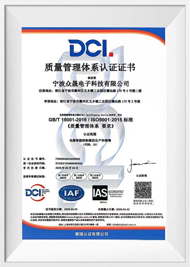
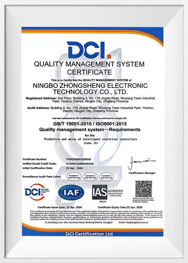
Certificate Of Honour
Latest News
AC Electric Fan PCB Industry knowledge
What B2B Buyers Should Know Before Sourcing an AC Electric Fan PCB
A well-matched AC Electric Fan PCB is the control board that switches an AC fan motor between speed steps, drives the oscillation motor, runs timers, and protects the fan during overheating or electrical faults. The short answer for buyers is that a good board delivers consistent speed steps, quiet switching, sound thermal protection, and a layout that can be adapted to your fan design and target market. In stand fans, tower fans, desk fans, and wall-mounted fans, this board sits between the user and the motor, so every button press, remote command, and timer setting passes through it.
This is why fan brands, private-label owners, and contract manufacturers often look for an AC Electric Fan PCB Factory that handles circuit design, firmware, assembly, and testing under one roof. In the sections below, we cover which criteria buyers rank highest, what the board controls, how demand splits across fan types, how relay-based and triac-based boards compare, how temperature rises with speed, and where quality checks are focused. The aim is practical: help you prepare a clear brief for an AC Electric Fan PCB Supplier and ask the right questions before requesting a sample.
The Sourcing Criteria Buyers Rank Highest for Fan Control Boards
When procurement and engineering teams compare suppliers, a familiar set of criteria keeps coming up. The horizontal bar chart below shows an indicative importance index, scaled from 0 to 100, based on priorities commonly raised during supplier evaluations for electric fan control boards. Speed step consistency sits at the top, because users expect the same airflow every time they select the same setting. Thermal and overheat protection follows closely, since a fan can run for many hours a day in warm rooms and needs a board that handles heat well. Electrical safety and insulation comes next, as the board works directly with mains voltage and must meet the rules of each target market. Quiet switching, relay and switch life, and customization flexibility complete the list, and the last of these often decides which supplier wins a long-term cooperation once the technical basics are met. Treat the chart as a planning aid rather than a fixed ranking, because each product and market weighs these items a little differently.
The practical lesson is that the top items are technical and testable, while the bottom ones are about how well a supplier works with your team. A reliable AC Electric Fan PCB Factory will show speed step test records, temperature rise data, safety test results, and a clear process for sampling, engineering changes, and delivery scheduling.
What the Control Board Does Inside an Electric Fan
An electric fan looks simple from the outside, yet the control board handles several jobs at once. It reads the buttons or the remote, selects the correct motor winding or power level for the chosen speed, drives the oscillation motor, and counts down the timer. It also watches for fault conditions and cuts power when something goes outside the safe range. Because the board connects the user to every moving part, its design decides how the fan feels in daily use, from the click of a speed change to the way the fan shuts off at the end of a timer.
Main Functions of an AC Electric Fan PCB
| Function Block | What It Does | Why It Matters |
|---|---|---|
| Speed Control | Switches motor winding taps or adjusts power with relays or triacs | Clear, repeatable speed steps |
| Oscillation Control | Drives the swing motor on and off | Wider air coverage in the room |
| Timer and Auto Off | Counts down a preset period and stops the fan | Convenient overnight use |
| Remote and Panel Interface | Reads touch keys, buttons, infrared, or radio commands | Smooth user experience and modern feel |
| Protection Circuit | Handles overheating, surges, and abnormal current | Supports safe operation in warm rooms |
A short specification list helps a supplier quote and design faster. Most projects start by defining the following points:
- Rated input voltage and frequency for each target market.
- Motor type, number of speed taps, and rated current of each output.
- Oscillation motor type and any extra loads such as lighting or ionizers.
- Panel layout, display type, and remote control requirements.
- Housing dimensions, mounting points, and connector positions.
Which Fan Types Use These Control Boards
Knowing where these boards are used helps buyers decide on board size, output rating, and panel style. The column chart below shows an indicative split of control board demand by fan type, based on common patterns in household fan manufacturing. Stand fans take the largest share, since they offer a good balance of airflow, height adjustment, and oscillation. Tower fans follow, where slim housings call for compact boards and neat panel layouts. Desk and table fans come next, with a focus on simple operation and small board size. Wall-mounted and box fans account for a smaller portion, while other designs make up the remainder. The mix varies by region and season, so treat it as a starting point for discussion rather than a forecast.
For a factory that serves fan brands and OEM customers, this mix explains why a modular board platform is valuable. An AC Electric Fan PCB Supplier that can reuse a proven core circuit while adjusting the output rating, panel layout, connectors, and protection features for each fan type shortens development time and keeps quality consistent across the range.
Relay-Based Boards Versus Triac-Based Boards
Buyers often ask how to choose between a relay-based speed control board and a triac-based one, and the radar chart below compares the two across five dimensions: speed resolution, quiet operation, circuit simplicity, switch life, and EMI control. The triac-based board reaches further on speed resolution, quiet operation, and switch life, because it switches electronically without moving contacts and can offer finer speed steps. The relay-based board reaches further on circuit simplicity and EMI control, since a relay simply connects one motor tap at a time and does not chop the waveform. Neither shape fills the chart, which is the real message: each approach suits a different product position. A fan built for a quiet bedroom may lean toward a triac design, while a straightforward model with fixed speed taps may suit a relay design well. The scores are illustrative and meant to support a discussion about product positioning.
For a fan brand, the chart suggests a simple selection rule: choose a triac-based design where fine speed steps, quiet switching, and long switch life support the product story, and keep a relay-based design for simpler models. An AC Electric Fan PCB Factory that builds both can compare them against your target market and feature list.
How Board Temperature Rises with Fan Speed
Heat is one of the main design topics for any board that works with mains-powered loads. The line chart below shows an illustrative temperature rise on the board across five speed steps, measured above the surrounding room temperature. At the lowest step, the motor current is small and the board stays only a few degrees above ambient. As the speed increases, the current rises and so does the heat generated by relays, triacs, and power components. A smooth, gradual climb is a healthy sign, because it shows the thermal design has room to spare at the highest step. A sudden jump at one step would suggest a weak point, such as a narrow copper path or a component working near its limit. These figures are illustrative, and real results depend on the motor, housing airflow, and layout, so buyers should ask for temperature rise data measured inside the real fan housing.
In this example, the rise moves from about 6 degrees at the lowest step to roughly 24 degrees at the highest step, a smooth and predictable pattern. When you request samples, ask the supplier how temperature is measured, which room temperature is used, and how long the fan runs before the reading is taken, so the thermal claims in your product materials match what you can support with data.
Where Quality Checks Focus in Fan Board Production
Quality in a fan control board is built into the process rather than inspected in at the end. The donut chart below shows an indicative split of quality check effort across the main control areas in a typical production flow. Insulation and safety tests take the largest slice, because the board works with mains voltage and needs consistent isolation. Speed and oscillation function tests come next, covering every speed step, the swing output, the timer, and the remote receiver. Soldering and optical inspection follows, since solder quality decides long-term reliability, especially on high-current joints. Burn-in and aging tests, along with packaging and labeling checks, make up the remainder. Seeing the effort laid out this way helps buyers ask better audit questions, such as how safety tests are sampled and how results are recorded for later traceability.
A supplier with documented procedures in each of these areas makes it easier for your own quality team, or a third-party inspector, to verify results. Batch records, component traceability, and clear corrective action steps are good signs of a mature operation, and they matter whether the order is for a single board model or a full family of fan controllers.
Working with a Custom Board Partner from Concept to Shipment
A smooth project usually follows a predictable path. It starts with a brief covering the fan type, input voltage, motor data, number of speed steps, oscillation and timer needs, panel layout, and target certifications. The factory then proposes a circuit and layout or adapts an existing platform, followed by sample boards that are tested on your actual fan and housing. After the sample is approved, pilot production confirms that the design holds up at volume, with attention to solder quality and output consistency. Mass production and final inspection come next, and the project closes with packing, documentation, and shipping coordination.
What helps most on the buyer side is sharing the motor and housing samples early, together with a clear specification for speed steps, timer options, and safety scope. What helps most on the factory side is in-house capability across circuit design, firmware, assembly, and testing, which shortens the loop when a sample needs a tweak, such as a new timer option, a revised thermal threshold, or an updated panel layout. A trusted AC Electric Fan PCB partner that handles these steps in-house can keep the buyer informed with test data, revised drawings, and sample photos at each stage, which is especially useful for brands that run several product lines at once.
About Ningbo Zhongsheng Electronic Technology Co., LTD.
Ningbo Zhongsheng Electronic Technology Co., LTD. was established in 2015 and is located in the beautiful port city of Ningbo. We are a China Custom Intelligent Control Boards Manufacturer and PCB Board Factory, specializing in the research and manufacturing of intelligent control systems for household appliances. We focus on the full-chain services of intelligent control boards and electronic products, from research and development to manufacturing, always adhering to the core concepts of "high cost-effectiveness" and "smart living".
For fan brands looking for a dependable AC Electric Fan PCB Supplier, this full-chain approach, covering research, design, production, assembly, and testing, offers a practical starting point. Working with a team that understands both household appliance behavior and electronic control helps connect the board with the motor, housing, and user experience of the finished fan.
Frequently Asked Questions
Q1: What does an AC electric fan PCB do?
A1: It is the control board of the fan. It selects the speed step for the AC motor, drives oscillation, runs the timer, reads the panel or remote, and handles protection functions.
Q2: Can the board be customized for my fan?
A2: Yes. Board size, speed steps, output rating, timer options, panel layout, connectors, and remote interface can usually be adapted, subject to your fan design and the standards of your target market.
Q3: How is board reliability verified?
A3: Boards are typically checked through functional tests, insulation tests, burn-in under load, and inspection of solder joints, and the factory records the results so they can be reviewed batch by batch.
Q4: What should be checked on a sample before approving production?
A4: Check each speed step, oscillation, timer accuracy, remote response, switching noise, temperature rise inside the housing, and connector fit, and compare them with the agreed specification.
Q5: How should a buyer evaluate an AC electric fan PCB factory?
A5: Review test records, sample quality, component traceability, and communication responsiveness, and consider a factory audit or third-party inspection before mass production begins.

-
 No. 179, Jingda Road, Wanshan Town, Yinzhou District, Ningbo City, Zhejiang Province, China
-
 +86-15344609926
+86 13858226971 -
 +86 13858226971
+86 15344609926 -
 13858226971@163.com
PRODUCTS
QUICK LINKS
SOCIAL MEDIA
Copyright © Ningbo Zhongsheng Electronic Technology Co., LTD. All Rights
Reserved
AC Electric Fan PCB Supplier
OEM/ODM AC Electric Fan PCB Factory
