

 中文简体
 عربى

ZHONGSHENG
ZHONGSHENG
ZHONGSHENG
ZHONGSHENG
ZHONGSHENG
ZHONGSHENG
ZHONGSHENG
ZHONGSHENG
ZHONGSHENG
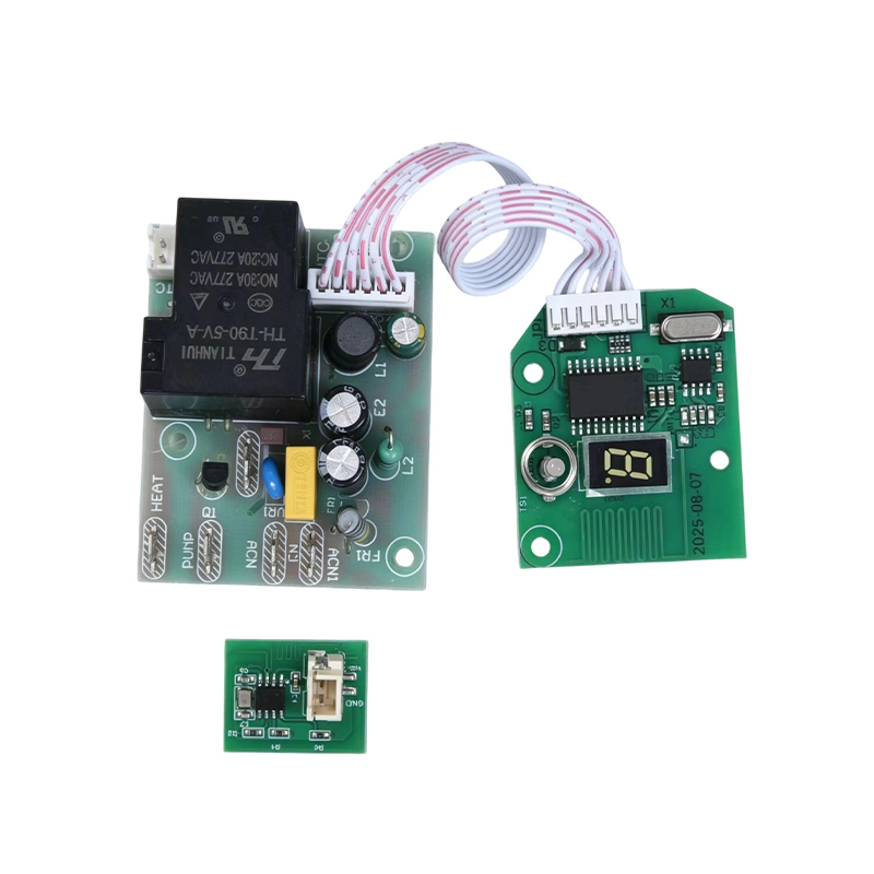
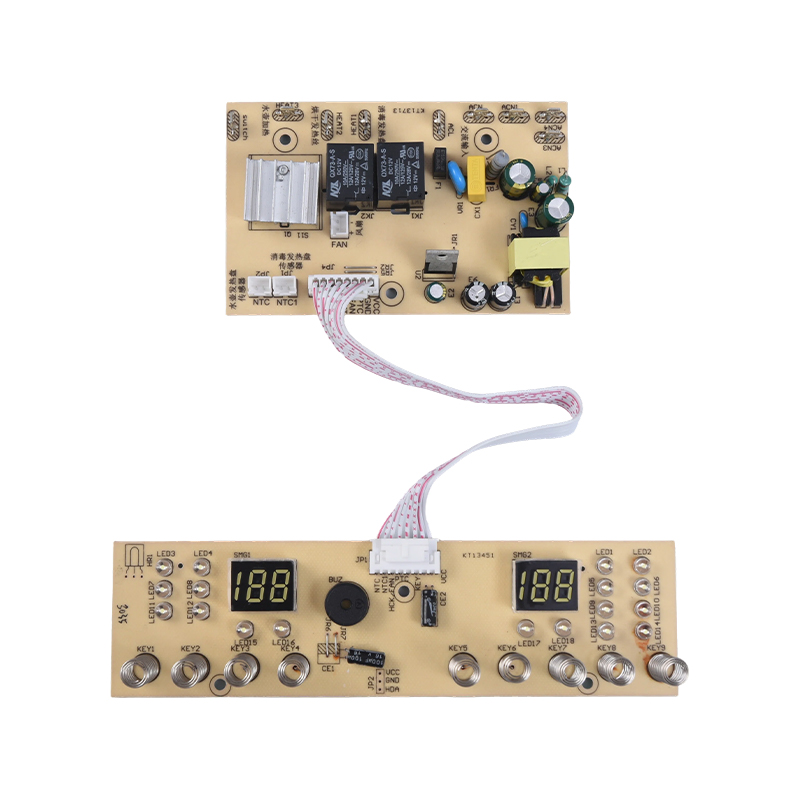
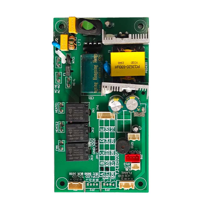
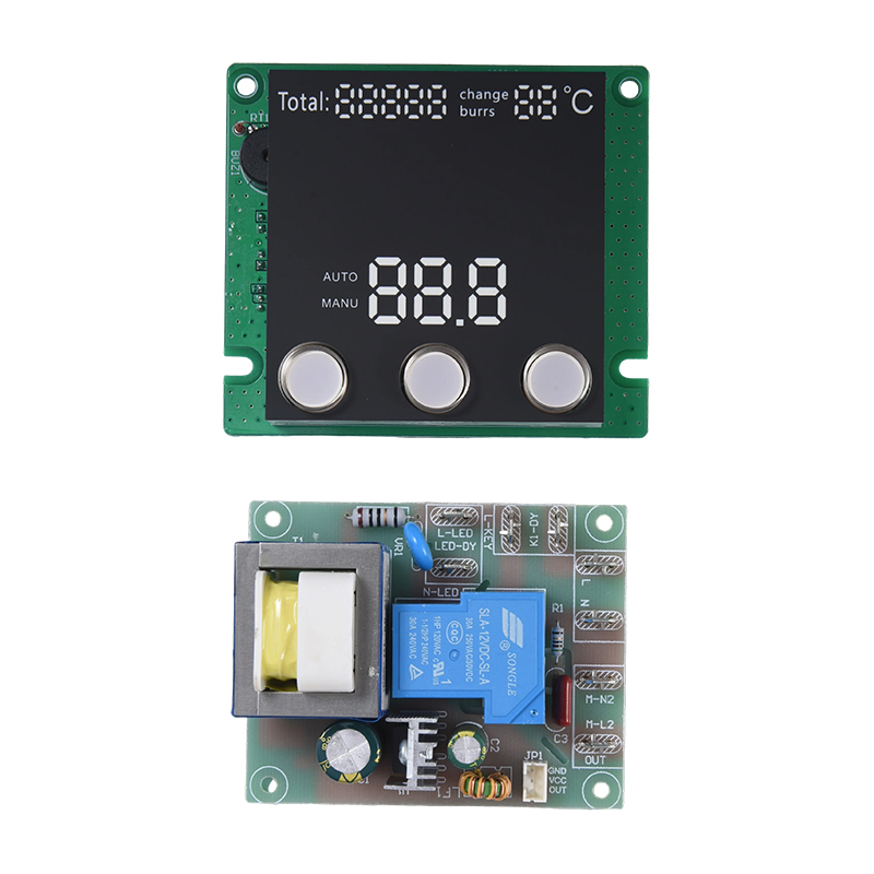
An Electric Fan PCB is the printed circuit board that acts as the brain of an electric fan. It takes the user command from a button, knob or remote control, then switches and regulates the power sent to the motor so the fan runs at the right speed, in the right mode and for the right time. Without this board, the fan motor has no intelligent control.
In a basic fan the board may only select between three speed windings. In a modern fan it also manages oscillation, timer, natural wind mode, display, buzzer feedback and protection against overcurrent or overheating. The more functions a fan offers, the more the PCB matters.
This guide explains what the board does, which types exist, which parts sit on it and how to judge quality, so that appliance brands and repair buyers can make a practical choice.
Content
- 1 What an Electric Fan PCB actually does
- 2 Main types of fan control boards
- 3 Core components on the board
- 4 Functions that modern fan boards support
- 5 Where Electric Fan PCBs are used
- 6 Design points that decide quality and safety
- 7 Common problems and how to recognize them
- 8 How to choose the right Electric Fan PCB
- 9 Key takeaways
- 10 Sources and references
What an Electric Fan PCB actually does
The board converts human input into motor action. Its work can be grouped into four jobs, shown in the table below.
| Job | What the board does | Typical example |
|---|---|---|
| Receive commands | Reads keys, knobs or an infrared or radio remote signal | Press speed up on the remote |
| Control the motor | Switches or regulates power to the fan motor | Change from low to high speed |
| Manage extra functions | Drives swing motor, timer, display and buzzer | Turn off after 2 hours |
| Protect the fan | Limits current, detects overheating and handles surges | Stop the motor when it stalls |
For a user, all of this is invisible. The fan simply responds smoothly when a button is pressed. For a manufacturer, the board decides how many features the product can offer and how long it will keep working.
Main types of fan control boards
The right board depends on the motor inside the fan. Two families dominate the market.
AC motor control boards
These boards drive a conventional AC induction motor. Speed is usually changed by switching relays between motor winding taps, or by phase control with a triac, a semiconductor switch that chops the AC waveform. They are simple, low cost and suitable for budget stand fans, table fans and wall fans.
DC and BLDC motor control boards
These boards include a driver stage and a microcontroller that commutates a brushless DC motor electronically. They allow many speed steps, quiet operation and lower power use. Energy agencies have reported large savings for this type. For example, India's Bureau of Energy Efficiency, in its public fan efficiency programs, has cited brushless DC ceiling fans using around 28 W against roughly 75 W for conventional fans of similar size. The exact saving depends on the model and speed setting.
| Feature | AC motor board | BLDC motor board |
|---|---|---|
| Speed steps | Usually 3 to 5 | Often 6 to 12 or stepless |
| Noise | Moderate, relay click possible | Very quiet |
| Power use | Higher | Lower |
| Board cost | Low | Higher |
| Best for | Entry level fans | Premium and energy saving fans |
Our Electric Fan PCB range can be matched to either motor family, so you do not need to change your fan structure to adopt a suitable board.
Core components on the board
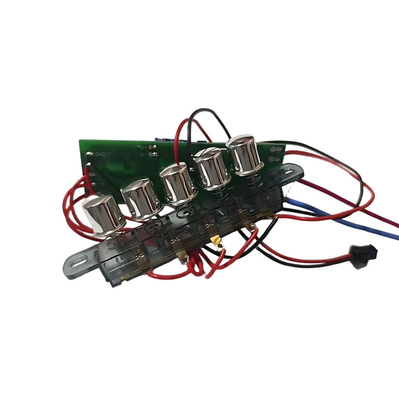
A typical fan board is small, but each part has a clear role.
- Microcontroller that reads inputs and decides the output state.
- Relays or triacs that switch the motor power.
- Power supply section that turns mains voltage into low voltage for the logic circuit.
- Infrared or radio receiver for remote control.
- Touch keys, buttons or knob interface and an LED or digital display.
- Buzzer for key feedback and alarm tones.
- Protection parts such as fuse, varistor and thermal protection.
- Zero-cross detection circuit on boards that use phase control, which helps reduce noise and electrical interference.
Functions that modern fan boards support
Consumers now expect more than a simple speed switch. A well-designed board can offer many functions without a large cost increase because most of them are handled in software.
Common user functions
- Multi-speed control, from low to high.
- Timer, commonly offered in steps from 30 minutes up to 8 hours.
- Oscillation or swing control through a separate swing motor.
- Natural wind mode, where speed rises and falls in a changing pattern.
- Remote control with memory of the last setting.
- Sleep mode that lowers speed and display brightness over time.
Protection functions
- Locked-rotor protection that cuts power when the blades are blocked.
- Overtemperature protection for the motor and board.
- Surge protection at the mains input.
Where Electric Fan PCBs are used
The same control principle appears in many fan products, but the board layout changes with the housing and the motor.
| Fan type | Typical board needs |
|---|---|
| Pedestal and stand fan | Speed, swing, timer, remote |
| Table and desk fan | Compact board, simple speed and swing |
| Tower fan | Display, timer, sleep mode, remote |
| Wall fan | Long cable layout, remote, swing |
| Ceiling fan | Remote or wall control, reverse function, light control |
| Rechargeable fan | Low voltage DC board with battery protection |
If your project fits one of these categories, you can review options on our Electric Fan PCB page and send us the motor and function details for a matched solution.
Design points that decide quality and safety
Two boards with the same function list can differ greatly in reliability. These design points are worth checking.
Safety and standards
Household fans fall under the IEC 60335 family, and the particular requirements for fans are in IEC 60335-2-80, published by the International Electrotechnical Commission. These documents cover items such as insulation, creepage distance between live parts and protection against overheating. Electrical noise from the motor and the board is addressed in CISPR 14-1, which sets emission limits for household appliances, and surge immunity is commonly tested under IEC 61000-4-5.
Thermal and electrical margin
Relays and triacs should be chosen with a clear current margin above the motor running and starting current. An undersized switch is one of the most common reasons for early failure in fans.
Manufacturing quality
Solder joint quality and board cleanliness can be judged against the acceptance criteria of IPC-A-610, a widely used workmanship standard for electronic assemblies. Fans often run in warm and dusty rooms, so a protective coating on the board can also help extend service life.
Common problems and how to recognize them
When a fan misbehaves, the board is often the cause. The table lists frequent symptoms and likely board-related reasons. A technician should confirm the diagnosis, because the motor, capacitor or wiring can also be at fault.
| Symptom | Possible board-related cause |
|---|---|
| Fan does not start | Failed relay, blown fuse or power supply fault |
| Speed does not change | Damaged switch, key fault or microcontroller problem |
| Remote does not respond | Receiver fault or weak signal input |
| Fan stops by itself | Overheating protection or unstable supply |
| Swing does not work | Swing output stage or connector fault |
| Humming or clicking noise | Relay wear or poor triac control |
Replacing the whole control board is often the fastest and most reliable repair when several of these symptoms appear together.
How to choose the right Electric Fan PCB
Use the steps below to narrow the choice before requesting a quote or sample.
- Confirm the motor type, voltage and power rating of your fan.
- List the functions you need, such as speed steps, timer, swing and remote control.
- Check the available space and the mounting positions in the fan housing.
- Decide the control interface, for example buttons, touch keys, knob or remote only.
- Ask about safety design, protection functions and the test items for each batch.
- Request a sample and run it for a full day on your own fan before mass ordering.
Our engineering team can adjust layout, software functions and connectors to match your product. Details of the standard range are available on the zs-pcba.com product page for the Electric Fan PCB.
Key takeaways
An Electric Fan PCB is the control board that converts user commands into motor action and adds features such as timer, swing, remote control and protection. AC boards suit low cost fans, while BLDC boards suit quiet and energy saving models. Quality depends on component margin, safety design and workmanship, so these points deserve more attention than the function list alone.
Sources and references
- IEC 60335-1 and IEC 60335-2-80, safety of household electrical appliances and particular requirements for fans (International Electrotechnical Commission).
- CISPR 14-1, electromagnetic compatibility, emission requirements for household appliances (International Electrotechnical Commission).
- IEC 61000-4-5, surge immunity testing (International Electrotechnical Commission).
- IPC-A-610, acceptability of electronic assemblies (IPC).
- Bureau of Energy Efficiency, India, public information on energy efficient brushless DC ceiling fans, which cites about 28 W against about 75 W for conventional fans. Please verify the latest figures on the agency website before quoting them.
- Speed step ranges and application tables are general industry practice summarized by our engineering team, not results of a published study.